Ensuring Safety and Performance in Photovoltaic Systems
Solar energy systems are marvels of modern engineering, quietly converting sunlight into clean electricity day after day. But like any complex system, they face unique challenges that require careful attention. One of the most critical yet often overlooked aspects is reverse current tolerance – the system's ability to handle situations where current flows backward through panels. When solar panels become shaded or faulty, instead of generating power, they can actually consume power from other panels in the string. This reverse flow creates hotspots that can irreversibly damage solar modules over time.
Consider this real-world scenario: In a typical residential setup in Arizona, partial shading from a newly installed satellite dish caused reverse current in just two panels. Within six months, this led to a 15% efficiency drop and nearly $1,200 in replacement costs. Situations like this are why comprehensive testing isn't just recommended – it's essential for both safety and long-term performance. These tests help catch problems early, ensuring your solar investment delivers maximum returns for years to come.
As solar installations grow more complex and scale increases, the risk of reverse current damage escalates exponentially. New technologies like bifacial modules and high-density panel configurations have made reverse current management increasingly challenging. But beyond financial loss, poorly managed reverse current poses genuine safety hazards:
The good news? Proper reverse current testing according to established standards helps catch these issues before they escalate. Just as you wouldn't drive a car without brakes, you shouldn't operate a solar array without verifying its reverse current tolerance.
Reverse current testing is essentially a stress test for your solar panels' "immune system." By deliberately creating controlled reverse current scenarios, we assess how well your modules can protect themselves from real-world conditions like partial shading, debris accumulation, or unexpected equipment failures.
The gold standard for PV system testing, IEC 62446-1 establishes comprehensive guidelines for both initial verification and periodic maintenance. Its tiered approach ensures appropriate testing rigor for systems of all sizes:
These complementary standards focus specifically on module safety and performance thresholds. They establish baseline reverse current tolerances that manufacturers must meet through rigorous design validation testing.
The UL standard adapts international guidelines for the North American market with specific requirements for fire safety, electrical isolation, and reverse current failure modes unique to regional installation practices.
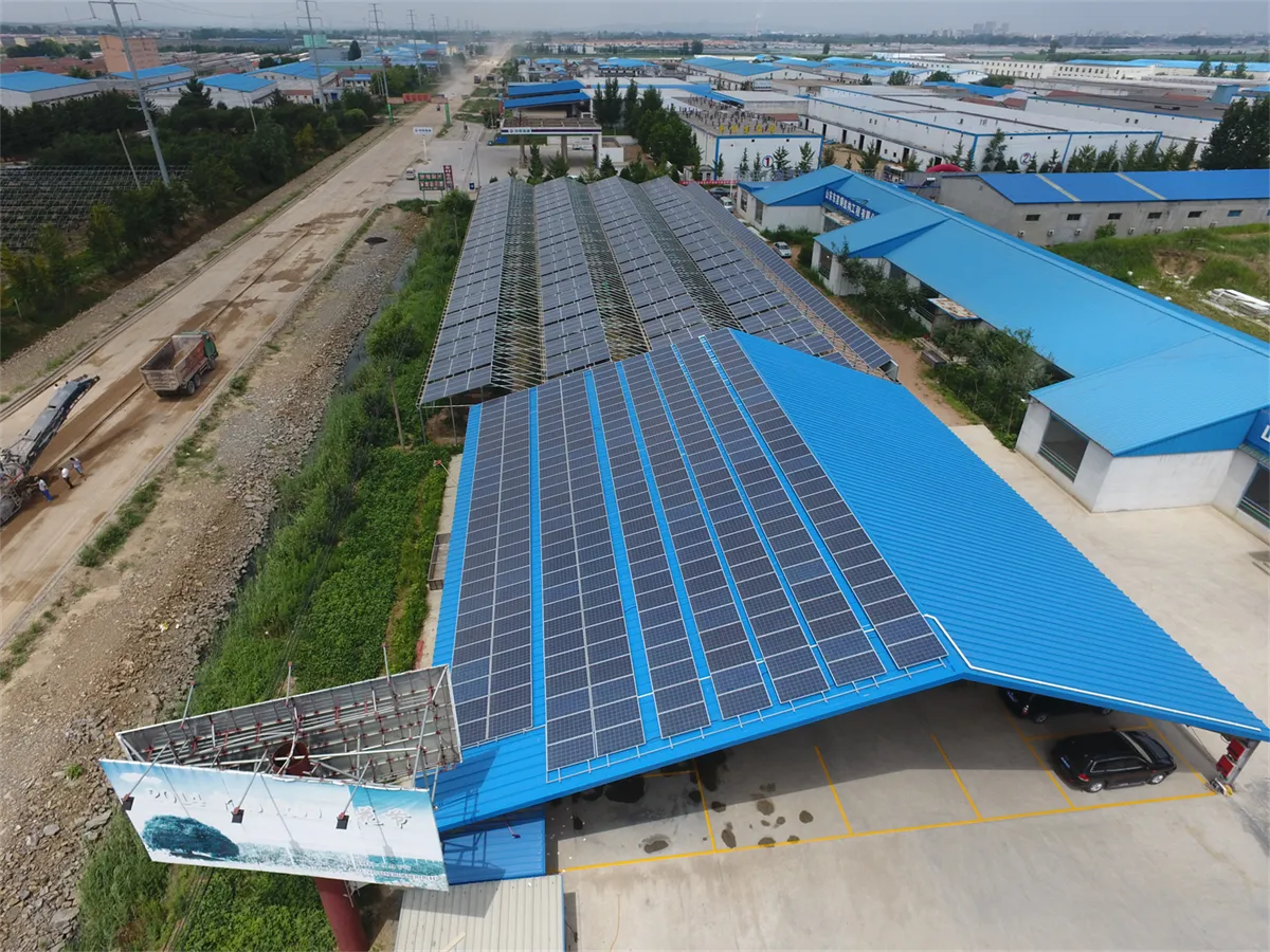
Effective reverse current testing is both an art and science. The following comprehensive procedure ensures you capture all critical aspects while maintaining safety:
Using a calibrated digital multimeter, measure VOC for each string. Compare against manufacturer specifications (typically within ±5%). Significant deviations indicate potential bypass diode failures contributing to reverse current vulnerability.
Apply test voltage (usually 500-1000VDC) between live conductors and earth. Minimum acceptable readings vary by system voltage but generally should exceed 1 MΩ. Poor insulation allows reverse current pathways to ground.
Under partial shading simulation, use thermal imaging to confirm even heat distribution. Temperature variations exceeding 15°C indicate diode malfunction. Diode failures account for 70% of reverse current issues according to NREL field studies.
Field Insight: Always test at dawn when temperatures are consistent across modules. Midday testing creates false positives due to microclimate temperature variations across array surfaces.
The core validation involves creating controlled reverse current scenarios:
Passing criteria vary by module class but typically require:
Systems showing values beyond these thresholds require immediate remediation, which may include diode replacement, string reconfiguration, or in severe cases, module replacement.
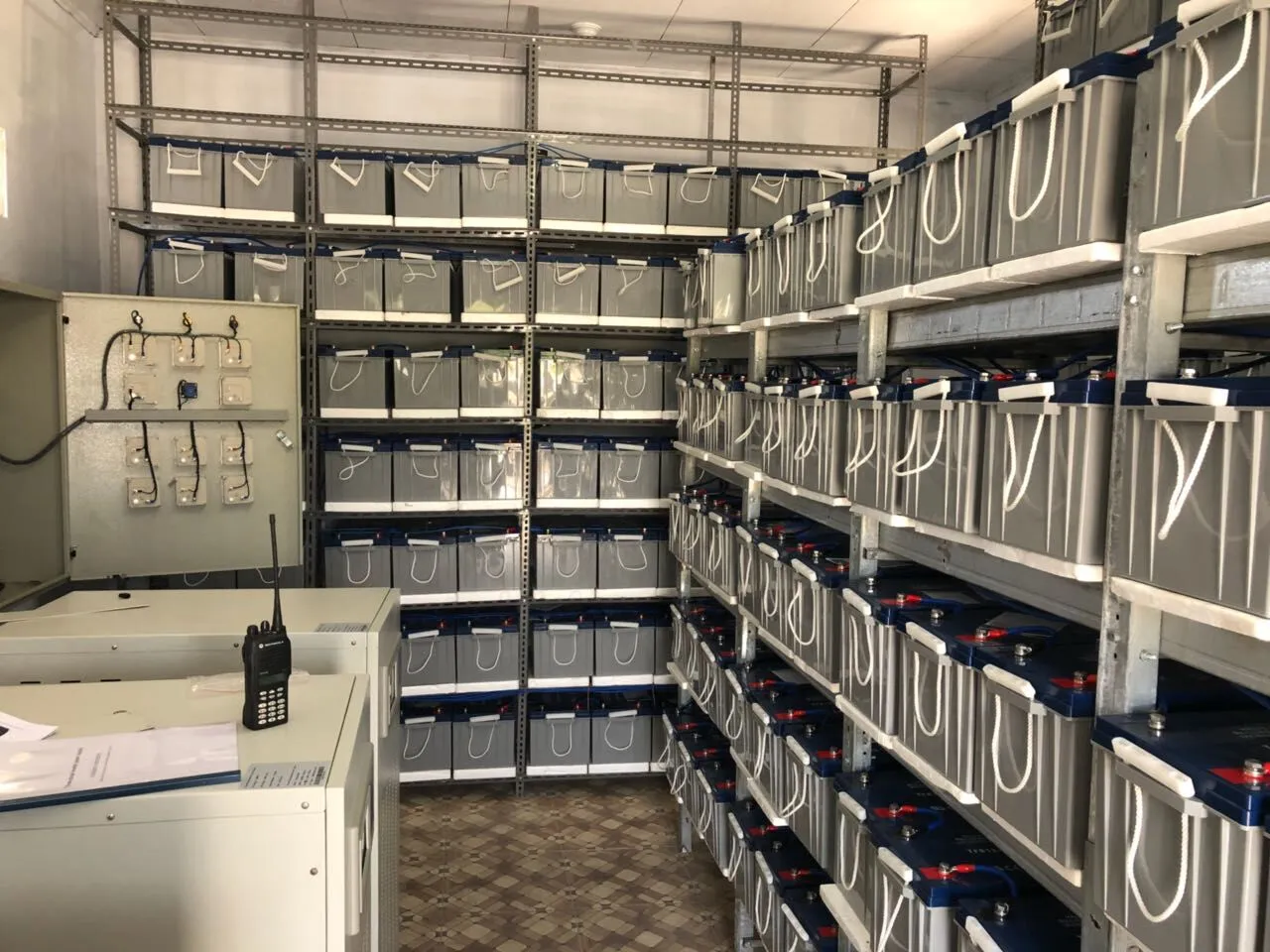
For complex installations, basic compliance testing isn't enough. These advanced techniques provide deeper insights:
Using specialized curve tracers, technicians map voltage-current characteristics at the cell, module, and string levels. Characteristic "steps" in the curve reveal reverse current paths and quantify power loss percentages.
This sophisticated method applies low current at night to make solar cells "glow." Dark spots indicate microcracks and cell failures that create reverse current paths. An image speaks a thousand words:
Electroluminescence reveals reverse current damage hotspots not visible to the naked eye.
Smart monitoring systems now incorporate reverse current detection algorithms. They analyze performance data to identify deteriorating conditions long before measurable power loss occurs, creating preventive maintenance opportunities.
Despite clear standards, technicians encounter real-world challenges in reverse current testing:
| Challenge | Practical Solution |
|---|---|
| Inaccessible rooftop installations | Portable IV testers with 20m wireless range |
| Intermittent shading patterns | Time-lapse thermal camera studies |
| Multi-inverter complications | Distributed micro-inverters with per-panel monitoring |
Beyond these technical solutions, documentation and communication are equally important. Implementing standardized testing forms with clear pass/fail criteria eliminates ambiguity, while photographic evidence of test points creates reliable maintenance records.
Maintenance Tip: Schedule reverse current tests during the second year after installation when early failures manifest, then every 5 years unless issues arise. Immediately after extreme weather events, conduct spot checks on vulnerable modules.
While testing catches existing problems, smart design prevents them entirely. These installation best practices drastically reduce reverse current risks:
Additionally, module-level power electronics (MLPEs) like optimizers and microinverters transform reverse current protection from passive to active systems, automatically isolating troubled panels before damage occurs.
Standards evolve as technology advances. Exciting developments on the horizon include:
But for today's installations, consistent adherence to IEC 62446-1 remains your most reliable protection. Like seatbelts in cars or smoke detectors in buildings, reverse current testing is a fundamental safety practice that protects both your equipment and your investment.
Remember: A properly tested solar installation isn't just a power generator – it's a reliable partner in sustainable energy production for decades to come. By implementing these comprehensive reverse current testing protocols, you ensure your system performs at its best, safely and efficiently, through changing conditions and the passing years.
Whether you're a homeowner monitoring your rooftop system or a technician servicing utility-scale farms, reverse current tolerance testing creates peace of mind. Those measurements you take today protect tomorrow's production, ensuring clean energy flows unhindered for years to come.
Recommend Products