
Understanding thermal dynamics for better component reliability and system safety
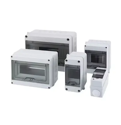
Distribution boxes are the unsung heroes of our electrical infrastructure. Hidden away in industrial settings or mounted discreetly on street poles, they quietly manage the flow of power to homes, businesses, and essential services. But there's a silent threat lurking inside these metal cabinets – heat. As electrical current flows through components, it naturally generates warmth, much like how your phone gets warm during extended use. But when that heat builds up unchecked, things get dangerous.
Think of the last time you touched a device that was too hot – that discomfort is multiplied a thousandfold inside a distribution box. Excessive heat accelerates component aging faster than time itself. Insulation materials become brittle, metals fatigue, and connections loosen. In extreme cases, this can lead to catastrophic failures like fires or power outages that ripple through entire communities. Remember that neighborhood blackout last summer? Chances are it started with an overheated component in a distribution box somewhere upstream.
Heat generation in electrical components follows Joule's first law – it's literally the energy tax we pay for moving electrons. The formula is simple: Heat = I²R. Translation: the power wasted as heat equals current squared times resistance. What this means practically is that small increases in current or resistance can lead to explosive growth in heat output.
Many technicians still rely on handheld infrared thermometers for spot checks. While they're useful for identifying hot spots, they're like trying to understand ocean currents by looking at a single wave. Comprehensive thermal testing requires a more sophisticated approach that reveals the entire thermal landscape inside the box.
The most effective temperature tests:
Cutting-edge approaches now employ something called tensor block-matching . Imagine having thermal images of your distribution box taken from multiple angles, then having a computer reassemble them into a detailed 3D heat map. This non-intrusive technique creates a virtual thermal model of the entire enclosure without needing physical access to every component.
The methodology follows two distinct stages:
Using strategically placed external sensors, technicians capture thermal patterns across the cabinet's exterior surfaces. Advanced algorithms then compare these patterns against a vast library of known thermal signatures – like facial recognition for heat patterns. The system finds the closest matches and uses them to reconstruct a preliminary 3D temperature model of the internal components. It's like hearing a complex symphony and being able to reconstruct the sheet music.
The initial thermal model gets upgraded through tensor super-resolution – essentially a heat map version of turning a blurry photo into a sharp image. The algorithm fills in the gaps and removes distortions, revealing the true temperature gradients around each busbar, circuit breaker, and connection point. What emerges is a crystal-clear thermal portrait of the distribution box's interior.
Like a doctor reading an X-ray, an experienced engineer can diagnose a distribution box's health by studying its thermal signature. Here's what those colors and patterns actually mean:
The Healthy Pattern: When everything's working as it should, you'll see consistent, moderate temperatures throughout the box. Connection points appear slightly warmer than surrounding areas – typically no more than 10-15°C above ambient temperature. This indicates balanced current distribution and proper contact pressure.
The Trouble Spots: Isolated bright hotspots indicate connection problems. Maybe a lug screw has worked itself loose over years of thermal cycling, or oxidation has built up on a contact surface. These small irregularities can create dangerous resistance points. Surprisingly, they're often missed during routine inspections because they can develop in hard-to-see locations.
The Aging Component Signature: When entire sections run hotter than expected, it usually indicates aging equipment. Circuit breakers whose trip mechanisms have weakened may not trip until their enclosures are dangerously hot. Transformers with deteriorated insulation show distinctive heat patterns that warn of imminent failure.
Once you've identified the thermal trouble spots, the real work begins – bringing those temperatures down. The solutions range from simple fixes to complete redesigns, but they all share a common goal: keeping electrons flowing without setting anything on fire.
Practical heat dissipation approaches:
Natural convection cooling often gets overlooked but remains surprisingly effective. Simply arranging components to create chimney effects can drop temperatures by 10-15% without additional energy costs. I once saw a technician solve a persistent heating problem just by rotating a power supply module 90 degrees to align with airflow.
For more challenging thermal management problems, active cooling might be necessary. But before installing noisy fans, consider more elegant solutions:
These clever compounds absorb large amounts of heat as they melt, then release it as they resolidify. Strategically placed phase change panels act like thermal shock absorbers during peak loads. They're maintenance-free and silent – the perfect solution for noise-sensitive environments.
An electrical substation serving a hospital complex kept experiencing mysterious voltage drops every afternoon during summer months. Technicians had checked everything – cables, transformers, switchgear – all tested fine. When they finally performed temperature rise testing, the culprit emerged: a main distribution panel that became a thermal bottleneck as air conditioning loads peaked.
The thermal imaging revealed how heat would back up through the system like traffic congestion. Circuit breakers were operating at 85°C – 30°C higher than specification during afternoon peaks. The solution involved adding ventilation louvers and upgrading to silver-plated contacts. The result? Zero afternoon voltage drops and a 15% reduction in the hospital's energy bill.
Another dramatic example came from an offshore wind farm. Salt air had corroded connection points inside turbine distribution cabinets, creating subtle hot spots invisible during routine inspections. Thermal testing during simulated storm conditions revealed several connections approaching melting point. Preventive replacement avoided what would have been a multimillion-dollar repair operation requiring a specialized marine crew.
You don't need NASA's budget to implement effective thermal monitoring. Here's how to build temperature testing into your maintenance strategy:
Start when equipment is new or recently refurbished. This establishes a "thermal fingerprint" to compare against future readings. Be sure to test under various load conditions – minimum, normal, and peak.
Conduct follow-up tests annually or whenever you notice abnormal operation. Digital twins now allow technicians to compare current heat patterns against the baseline and track minute changes over time.
After any significant electrical event – lightning strikes, sudden load changes, or even minor faults – perform thermal testing. Transient events can weaken connections without causing immediate failure.
Modern thermal diagnostics produce quantifiable data that transforms decision making from guesswork to precision engineering. We now track thermal indicators as fundamental as voltage and current measurements. The numbers don't lie – a 15% temperature increase at a connector correlates to a 500% reduction in expected service life.
Temperature rise testing isn't a luxury or academic exercise – it's fundamental to protecting electrical infrastructure. The evidence speaks clearly: systems maintained with thermal awareness consistently demonstrate:
•
50% fewer unexpected failures
• Component lifespans extended by 3-7 years
• Up to 9% reduction in energy losses
• Elimination of fire hazards before they ignite
The beauty of modern thermal testing is how accessible it's become. What once required specialized equipment and advanced degrees can now be performed with handheld thermal imagers and tablet-based analysis software. These advancements make comprehensive thermal management achievable for operators of any scale.
Remember that every degree matters. A seemingly insignificant 5°C increase in operating temperature translates to dramatically accelerated aging. But with the testing approaches we've discussed today, we can spot those small temperature changes before they snowball into catastrophic failures.
Next time you walk past a nondescript distribution cabinet, think about the thermal drama unfolding inside. Through careful temperature monitoring and strategic cooling solutions, we can ensure these vital components keep electrons flowing smoothly without hitting the thermal panic button.
Recommend Products