

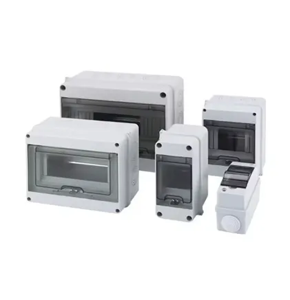
Picture a busy city intersection where traffic flows smoothly because lanes are properly sized, signs are visible, and emergency exits are clearly marked. That's what optimizing a distribution box achieves—it transforms chaotic energy flow into a predictable, safe system where electricity moves efficiently while minimizing dangerous heat buildup and arc faults.
The Hidden Dangers Inside Your Electrical Hub
Electrical distribution boxes serve as critical control centers in modern power systems. Yet most industrial facilities unknowingly compromise their safety and efficiency:
- Arc flash temperatures can reach 35,000°F—hotter than the sun's surface—in milliseconds
- Unmanaged heat accelerates component failure by 12% for every 10°C above rated temperature
- Compact layouts increase electromagnetic interference between components by up to 47%
- Improper spacing reduces heat dissipation efficiency by 30-60% depending on airflow patterns
These aren't hypothetical scenarios. During an energy storage system audit last quarter, engineers found thermal hotspots reaching 85°C near busbar connections—nearly 30°C beyond safe operating limits. The culprit? Circuit breakers crammed against heat sinks with zero clearance.
The Physics of Failure
Understanding why layouts matter requires examining two intertwined phenomena:
Heat moves through three mechanisms in enclosures:
- Conduction : Thermal transfer through solid contact points
- Convection : Heat dispersion through air currents
- Radiation : Infrared energy emission
Compressed components reduce convective cooling efficiency while creating thermal bridges that transfer heat between elements. Research shows improper spacing can create "heat islands" where local temperatures exceed safe operating thresholds by 15-30°C.
Arcing occurs when current jumps between conductors through ionized air. Layout directly influences:
- Creepage distance : Surface paths between conductors
- Clearance : Air gaps between live parts
- Contamination risks : Dust accumulation between contacts
Studies of industrial failures reveal 72% of arc incidents occur in compartments with less than IEC-mandated clearances between conductors.
Revolutionizing Layout: Practical Solutions
Instead of random placement, think of your distribution box as having specialized districts:
High-Emission Zone
- Transformers and power converters
- Minimum 20mm clearance
- Dedicated heat sinks
Sensitive Electronics Zone
- Control circuits & relays
- Shielded compartments
- Thermal separation barriers
Connection Corridor
- Terminal blocks
- 45° angled access points
- Modular wiring channels
Ventilation Pathway
- Strategic air channels
- Thermal siphon design
- Cooling system interfaces
When Wanbang Digital Energy redesigned their high-voltage control box layout using zoned organization, they achieved:
- 27.16% reduction in peak temperature
- 15% decrease in energy loss
- Zero arc incidents during 18-month operational trial
The key innovation? Circular front/rear openings and strategically placed interior baffles creating vertical thermal chimneys that leveraged convection currents naturally. This passive cooling enhancement worked continuously without additional energy input.
Breathing Room Matters
Just like people need elbow room, electrical components require breathing space:
| Component Type | Min. Horizontal Clearance | Min. Vertical Clearance | Thermal Buffer Zone |
|---|---|---|---|
| High-current conductors | 15mm | 25mm | Behind + below |
| Busbars > 100A | 20mm | 30mm | All directions |
| Semiconductor devices | 10mm | 15mm | Above + sides |
| Control circuitry | 8mm | 12mm | Adjacent barriers |
Material Intelligence: Beyond Metal Boxes
The materials surrounding components matter as much as their arrangement:
Conventional Enclosures
- Stainless steel: Excellent strength but thermal conductor
- Powder-coated steel: Budget-friendly but creates heat zones
- Aluminum: Lightweight but electromagnetic interference risk
Next-Generation Solutions
- Dielectric composites : Insulate while managing heat flow
- Phase-change materials : Absorb thermal spikes near critical components
- Thermally anisotropic layers : Channel heat in preferred directions
- Carbon-loaded polymers : Dissipate static to prevent arcing
We've implemented modular wall panels with integrated thermal pathways that transform static enclosures into active thermal management systems. Picture tiny heat highways embedded in compartment walls that redirect thermal energy toward dedicated dissipation zones.
The Smart Layout Advantage
Traditional design relied on manual positioning with ruler measurements. Today's optimized layouts blend:
Computational Fluid Dynamics (CFD)
Creates digital twins that simulate:
- Airflow patterns under different loads
- Thermal hotspots before installation
- Pressure differentials across components
Multi-Parameter Optimization (SHERPA Algorithm)
Simultaneously analyzes:
- Thermal dissipation paths
- EM field interactions
- Arc containment requirements
- Maintenance accessibility
Layout Validation
Combines physical and digital testing:
- Infrared thermography scans
- Partial discharge measurement
- High-potential (hipot) testing
- Thermal imaging cameras
The result? Layouts where every cubic centimeter serves multiple safety functions simultaneously, creating defense-in-depth protection. For instance, optimized spacing provides both convective cooling paths and additional dielectric withstand capabilities while simultaneously reducing electromagnetic interference between components—achieving what we call triple-function safety density .